- Time Functions
- OID_GEN_CO_GET_TIME_CAPS
- Remarks
- Timeout detection and recovery (TDR)
- Overview
- Timeout detection in WDDM
- Preparation for recovery
- Desktop recovery
- Acquiring high-resolution time stamps
- QPC support in Windows versions
- WindowsВ XP and WindowsВ 2000
- WindowsВ Vista and Windows ServerВ 2008
- WindowsВ 7 and Windows ServerВ 2008В R2
- WindowsВ 8, WindowsВ 8.1, Windows ServerВ 2012, and Windows ServerВ 2012В R2
- Guidance for acquiring time stamps
- Virtualization
- Direct TSC usage
- Examples for acquiring time stamps
- Using QPC in native code
- Acquiring high resolution time stamps from managed code
- Using QPC from kernel mode
- General FAQ about QPC and TSC
- FAQ about programming with QPC and TSC
- Low-level hardware clock characteristics
- Absolute Clocks and Difference Clocks
- Resolution, Precision, Accuracy, and Stability
- Hardware timer info
Time Functions
The following functions are used with system time.
| Function | Description |
|---|---|
| GetSystemTime | Retrieves the current system date and time in UTC format. |
| GetSystemTimeAdjustment | Determines whether the system is applying periodic time adjustments to its time-of-day clock. |
| GetTimeFormat | Formats a system time as a time string for a specified locale. |
| NtQuerySystemTime | Returns the system time. |
| RtlLocalTimeToSystemTime | Converts the specified local time to system time. |
| RtlTimeToSecondsSince1970 | Converts the specified system time to the number of seconds since the first second of January 1, 1970. |
| SetSystemTime | Sets the current system time and date. |
| SetSystemTimeAdjustment | Enables or disables periodic time adjustments to the system’s time-of-day clock. |
| SystemTimeToFileTime | Converts a system time to a file time. |
| SystemTimeToTzSpecificLocalTime | Converts a UTC time to a specified time zone’s corresponding local time. |
| TzSpecificLocalTimeToSystemTime | Converts a local time to a UTC time. |
The following functions are used with local time.
| Function | Description |
|---|---|
| EnumDynamicTimeZoneInformation | Enumerates dynamic daylight saving time information entries stored in the registry. |
| FileTimeToLocalFileTime | Converts a UTC file time to a local file time. |
| GetDynamicTimeZoneInformation | Retrieves the current time zone and dynamic daylight saving time settings. |
| GetDynamicTimeZoneInformationEffectiveYears | Retrieves a range, expressed in years, for which a DYNAMIC_TIME_ZONE_INFORMATION has valid entries. |
| GetLocalTime | Retrieves the current local date and time. |
| GetTimeZoneInformation | Retrieves the current time zone settings. |
| GetTimeZoneInformationForYear | Retrieves the time zone settings for the specified year and time zone. |
| RtlLocalTimeToSystemTime | Converts the specified local time to system time. |
| SetDynamicTimeZoneInformation | Sets the current time zone and dynamic daylight saving time settings. |
| SetLocalTime | Sets the current local time and date. |
| SetTimeZoneInformation | Sets the current time zone settings. |
| SystemTimeToTzSpecificLocalTime | Converts a UTC time to a specified time zone’s corresponding local time. |
| SystemTimeToTzSpecificLocalTimeEx | Converts a UTC time with dynamic daylight saving time settings to a specified time zone’s corresponding local time. |
| TzSpecificLocalTimeToSystemTime | Converts a local time to a UTC time. |
| TzSpecificLocalTimeToSystemTimeEx | Converts a local time with dynamic daylight saving time settings to UTC time. |
The following functions are used with file time.
| Function | Description |
|---|---|
| CompareFileTime | Compares two file times. |
| FileTimeToLocalFileTime | Converts a UTC file time to a local file time. |
| FileTimeToSystemTime | Converts a file time to system time format. |
| GetFileTime | Retrieves the date and time that the specified file or directory was created, last accessed, and last modified. |
| GetSystemTimeAsFileTime | Retrieves the current system date and time in UTC format. |
| LocalFileTimeToFileTime | Converts a local file time to a file time based on UTC. |
| SetFileTime | Sets the date and time that the specified file or directory was created, last accessed, or last modified. |
| SystemTimeToFileTime | Converts a system time to a file time. |
The following functions are used with MS-DOS date and time.
| Function | Description |
|---|---|
| DosDateTimeToFileTime | Converts MS-DOS date and time values to a file time. |
| FileTimeToDosDateTime | Converts a file time to MS-DOS date and time values. |
The following functions are used with Windows time.
| Function | Description |
|---|---|
| GetSystemTimes | Retrieves system timing information. |
| GetTickCount | Retrieves the number of milliseconds that have elapsed since the system was started, up to 49.7 days. |
| GetTickCount64 | Retrieves the number of milliseconds that have elapsed since the system was started. |
The following functions are used with high-resolution performance counters.
| Function | Description |
|---|---|
| QueryPerformanceCounter | Retrieves the current value of the high-resolution performance counter. |
| QueryPerformanceFrequency | Retrieves the frequency of the high-resolution performance counter. |
The following functions are used with the auxiliary performance counter.
| Function | Description |
|---|---|
| QueryAuxiliaryCounterFrequency | Queries the auxiliary counter frequency. |
| ConvertAuxiliaryCounterToPerformanceCounter | Converts the specified auxiliary counter value to the corresponding performance counter value; optionally provides the estimated conversion error in nanoseconds due to latencies and maximum possible drift. |
| ConvertPerformanceCounterToAuxiliaryCounter | Converts the specified performance counter value to the corresponding auxiliary counter value; optionally provides the estimated conversion error in nanoseconds due to latencies and maximum possible drift. |
The following function is used with interrupt time.
OID_GEN_CO_GET_TIME_CAPS
OID_GEN_CO_GET_TIME_CAPS is the same as OID_GEN_GET_TIME_CAPS.
The OID_GEN_CO_GET_TIME_CAPS OID requests a miniport driver to return its capabilities for reporting a NIC’s local time formatted as a GEN_GET_TIME_CAPS structure, which is defined as follows:
The members of this structure contain the following information:
Flags
The following flags can be ORed together. All unspecified flags must be set to zero.
READABLE_LOCAL_CLOCK
When set, indicates the presence of a readable clock on the NIC. Even without such a hardware clock, a miniport driver can use the system clock by calling NdisGetCurrentSystemTime, so long as it reports the correct precision in the ClockPrecision member.
CLOCK_NETWORK_DERIVED
When set, indicates that the NIC’s local time is derived from the network connection, as opposed to a free-running, onboard clock.
CLOCK_PRECISION
When set, indicates that the ClockPrecision member contains valid information.
RECEIVE_TIME_INDICATION_CAPABLE
When set, indicates that the NIC hardware can note the local time at which it receives the first cell of a received PDU and that the miniport driver propagates this receive time for each PDU when indicating the packet to a protocol.
TIMED_SEND_CAPABLE
When set, indicates that the NIC can schedule a packet for transmission according to its local time. Protocols can use NDIS_SET_PACKET_TIME_TO_SEND to set the TimeToSend timestamp in the out-of-band data block of a packet descriptor. Setting the timestamp does not affect when the packet is actually transmitted; instead, the timestamp is used for recordkeeping. A protocol driver can use the timestamp to determine how long it takes to complete the sending of a paket.
TIME_STAMP_CAPABLE
When set, indicates that the NIC can stamp (in the appropriate field of the outgoing packet) the time at which the first byte of the packet is transmitted and that the NIC can retrieve this time from the same field of an inbound packet.
ClockPrecision
Specifies the clock precision in parts per million. For this information to be considered valid, the CLOCK_PRECISION flag must be set.
Remarks
A miniport driver can provide support for certain timing parameters even in the absence of a local or network clock. In particular, a miniport driver can use the system clock for receive time indications, timed sends, and even time stamping. A NIC-based clock is better since it is likely to provide higher precision and to be accessible with lower latencies than the system clock. In all cases, the miniport driver must specify the precision of the clock that it uses. This allows protocols to determine how to best use the miniport driver’s timing support.
If the miniport driver reports the presence of a readable clock, it must be prepared to immediately respond to an OID_GEN_GET_NETCARD_TIME query. The miniport driver’s response to this call is time-critical and therefore must be synchronous.
Timeout detection and recovery (TDR)
This page describes timeout detection and recovery (TDR) for driver developers. See also TDR in Windows 8 and later for additional implementation details.
Overview
One of the most common stability problems in graphics occurs when a computer «hangs», or when it appears to be completely «frozen» while, in reality, it is processing an end-user command or operation. The user typically waits a few seconds and then decides to reboot the computer. The frozen appearance of the computer typically occurs because the GPU is busy processing intensive graphical operations, typically during game play, and hence does not update the display screen. TDRs enable the operating system to detect that the UI is not responsive.
The figure below shows the TDR process.
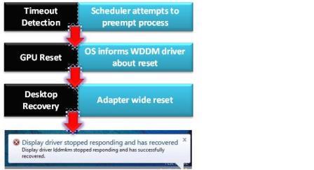
The operating system (OS) attempts to detect situations in which computers appear to be «frozen». The OS then attempts to dynamically recover from the frozen situations so that desktops are responsive again, alleviating the situation where end users needlessly reboot their systems.
If the OS detects that six (6) or more GPU hangs and subsequent recoveries occur within one (1) minute, the OS bug-checks the computer on the next GPU hang.
Timeout detection in WDDM
The GPU scheduler, which is part of the DirectX graphics kernel subsystem (Dxgkrnl.sys), detects that the GPU is taking more than the permitted amount of time to execute a particular task. The GPU scheduler then tries to preempt this particular task. The preempt operation has a «wait» timeout, which is the actual TDR timeout. The default timeout period in WindowsВ Vista and later operating systems is 2 seconds. If the GPU cannot complete or preempt the current task within the TDR timeout period, the OS diagnoses that the GPU is frozen.
To prevent timeout detection from occurring, hardware vendors should ensure that graphics operations (that is, direct memory access (DMA) buffer completion) take no more than 2 seconds in end-user scenarios such as productivity and game play.
Preparation for recovery
The GPU scheduler calls the display miniport driver’s DxgkDdiResetFromTimeout function to inform the driver that the OS detected a timeout. The driver must then reinitialize itself and reset the GPU. In addition, the driver must stop accessing memory and should not access hardware. The OS and the driver collect hardware and other state information that can be useful for post-recovery diagnosis.
See TDR in Windows 8 and later for additional implementation details.
Desktop recovery
The OS resets the appropriate state of the graphics stack. The video memory manager, which is also part of Dxgkrnl.sys, purges all allocations from video memory. The display miniport driver resets the GPU hardware state. The graphics stack takes the final actions and restores the desktop to the responsive state.
The only visible artifact from the hang detection to the recovery is a screen flicker. This flicker results when the OS resets some portions of the graphics stack, which causes a screen redraw. It is eliminated if the display miniport driver complies with WDDM 1.2 and later (see Providing seamless state transitions in WDDM 1.2 and later).
When the OS has successfully recovered the desktop, it does the following:
- Displays an informational message to the end user, saying «Display driver stopped responding and has recovered.»
- Logs the preceding message in the Event Viewer application and collects diagnosis information in the form of a debug report. If the end user opted in to provide feedback, the OS returns this debug report to Microsoft through the Online Crash Analysis (OCA) mechanism.
Some legacy DirectX applications might just render black at the end of this recovery, which requires the end user to restart these applications. Well-written DirectX 9Ex and DirectX 10 and later applications that handle Device Remove technology continue to work correctly. An application must release and then re-create its Microsoft Direct3D device and all of the device’s objects.
Acquiring high-resolution time stamps
Windows provides APIs that you can use to acquire high-resolution time stamps or measure time intervals. The primary API for native code is QueryPerformanceCounter (QPC). For device drivers, the kernel-mode API is KeQueryPerformanceCounter. For managed code, the System.Diagnostics.Stopwatch class uses QPC as its precise time basis.
QPC is independent of and isn’t synchronized to any external time reference. To retrieve time stamps that can be synchronized to an external time reference, such as, Coordinated Universal Time (UTC) for use in high-resolution time-of-day measurements, use GetSystemTimePreciseAsFileTime.
Time stamps and time-interval measurements are an integral part of computer and network performance measurements. These performance measurement operations include the computation of response time, throughput, and latency as well as profiling code execution. Each of these operations involves a measurement of activities that occur during a time interval that is defined by a start and an end event that can be independent of any external time-of-day reference.
QPC is typically the best method to use to time-stamp events and measure small time intervals that occur on the same system or virtual machine. Consider using GetSystemTimePreciseAsFileTime when you want to time-stamp events across multiple machines, provided that each machine is participating in a time synchronization scheme such as Network Time Protocol (NTP). QPC helps you avoid difficulties that can be encountered with other time measurement approaches, such as reading the processor’s time stamp counter (TSC) directly.
QPC support in Windows versions
QPC was introduced in WindowsВ 2000 and WindowsВ XP and has evolved to take advantage of improvements in the hardware platform and processors. Here we describe the characteristics of QPC on different Windows versions to help you maintain software that runs on those Windows versions.
WindowsВ XP and WindowsВ 2000
QPC is available on WindowsВ XP and WindowsВ 2000 and works well on most systems. However, some hardware systems’ BIOS didn’t indicate the hardware CPU characteristics correctly (a non-invariant TSC), and some multi-core or multi-processor systems used processors with TSCs that couldn’t be synchronized across cores. Systems with flawed firmware that run these versions of Windows might not provide the same QPC reading on different cores if they used the TSC as the basis for QPC.
WindowsВ Vista and Windows ServerВ 2008
All computers that shipped with WindowsВ Vista and Windows ServerВ 2008 used a platform counter (High Precision Event Timer (HPET)) or the ACPI Power Management Timer (PM timer) as the basis for QPC. Such platform timers have higher access latency than the TSC and are shared between multiple processors. This limits scalability of QPC if it is called concurrently from multiple processors.
WindowsВ 7 and Windows ServerВ 2008В R2
The majority of WindowsВ 7 and Windows ServerВ 2008В R2 computers have processors with constant-rate TSCs and use these counters as the basis for QPC. TSCs are high-resolution per-processor hardware counters that can be accessed with very low latency and overhead (in the order of 10s or 100s of machine cycles, depending on the processor type). WindowsВ 7 and Windows ServerВ 2008В R2 use TSCs as the basis of QPC on single-clock domain systems where the operating system (or the hypervisor) is able to tightly synchronize the individual TSCs across all processors during system initialization. On such systems, the cost of reading the performance counter is significantly lower compared to systems that use a platform counter. Furthermore, there is no added overhead for concurrent calls and user-mode queries often bypass system calls, which further reduces overhead. On systems where the TSC is not suitable for timekeeping, Windows automatically selects a platform counter (either the HPET timer or the ACPI PM timer) as the basis for QPC.
WindowsВ 8, WindowsВ 8.1, Windows ServerВ 2012, and Windows ServerВ 2012В R2
WindowsВ 8, WindowsВ 8.1, Windows ServerВ 2012, and Windows ServerВ 2012В R2 use TSCs as the basis for the performance counter. The TSC synchronization algorithm was significantly improved to better accommodate large systems with many processors. In addition, support for the new precise time-of-day API was added, which enables acquiring precise wall clock time stamps from the operating system. For more info, see GetSystemTimePreciseAsFileTime. On WindowsВ RT PC platforms, the performance counter is based on either a proprietary platform counter or the system counter provided by the WindowsВ RT PC Generic Timer if the platform is so equipped.
Guidance for acquiring time stamps
Windows has and will continue to invest in providing a reliable and efficient performance counter. When you need time stamps with a resolution of 1 microsecond or better and you don’t need the time stamps to be synchronized to an external time reference, choose QueryPerformanceCounter, KeQueryPerformanceCounter, or KeQueryInterruptTimePrecise. When you need UTC-synchronized time stamps with a resolution of 1 microsecond or better, choose GetSystemTimePreciseAsFileTime or KeQuerySystemTimePrecise.
On a relatively small number of platforms that can’t use the TSC register as the QPC basis, for example, for reasons explained in Hardware timer info, acquiring high resolution time stamps can be significantly more expensive than acquiring time stamps with lower resolution. If resolution of 10 to 16 milliseconds is sufficient, you can use GetTickCount64, QueryInterruptTime, QueryUnbiasedInterruptTime, KeQueryInterruptTime, or KeQueryUnbiasedInterruptTime to obtain time stamps that aren’t synchronized to an external time reference. For UTC-synchronized time stamps, use GetSystemTimeAsFileTime or KeQuerySystemTime. If higher resolution is needed, you can use QueryInterruptTimePrecise, QueryUnbiasedInterruptTimePrecise, or KeQueryInterruptTimePrecise to obtain time stamps instead.
In general, the performance counter results are consistent across all processors in multi-core and multi-processor systems, even when measured on different threads or processes. Here are some exceptions to this rule:
Pre-WindowsВ Vista operating systems that run on certain processors might violate this consistency because of one of these reasons:
- The hardware processors have a non-invariant TSC and the BIOS doesn’t indicate this condition correctly.
- The TSC synchronization algorithm that was used wasn’t suitable for systems with large numbers of processors.
When you compare performance counter results that are acquired from different threads, consider values that differ by В± 1 tick to have an ambiguous ordering. If the time stamps are taken from the same thread, this В± 1 tick uncertainty doesn’t apply. In this context, the term tick refers to a period of time equal to 1 Г· (the frequency of the performance counter obtained from QueryPerformanceFrequency).
When you use the performance counter on large server systems with multiple-clock domains that aren’t synchronized in hardware, Windows determines that the TSC can’t be used for timing purposes and selects a platform counter as the basis for QPC. While this scenario still yields reliable time stamps, the access latency and scalability is adversely affected. Therefore, as previously stated in the preceding usage guidance, only use the APIs that provide 1 microsecond or better resolution when such resolution is necessary. The TSC is used as the basis for QPC on multi-clock domain systems that include hardware synchronization of all processor clock domains, as this effectively makes them function as a single clock domain system.
The frequency of the performance counter is fixed at system boot and is consistent across all processors so you only need to query the frequency from QueryPerformanceFrequency as the application initializes, and then cache the result.
Virtualization
The performance counter is expected to work reliably on all guest virtual machines running on correctly implemented hypervisors. However, hypervisors that comply with the hypervisor version 1.0 interface and surface the reference time enlightenment can offer substantially lower overhead. For more information about hypervisor interfaces and enlightenments, see Hypervisor Specifications.
Direct TSC usage
We strongly discourage using the RDTSC or RDTSCP processor instruction to directly query the TSC because you won’t get reliable results on some versions of Windows, across live migrations of virtual machines, and on hardware systems without invariant or tightly synchronized TSCs. Instead, we encourage you to use QPC to leverage the abstraction, consistency, and portability that it offers.
Examples for acquiring time stamps
The various code examples in these sections show how to acquire time stamps.
Using QPC in native code
This example shows how to use QPC in C and C++ native code.
Acquiring high resolution time stamps from managed code
This example shows how to use the managed code System.Diagnostics.Stopwatch class.
The System.Diagnostics.Stopwatch class also provides several convenient methods to perform time-interval measurements.
Using QPC from kernel mode
The Windows kernel provides kernel-mode access to the performance counter through KeQueryPerformanceCounter from which both the performance counter and performance frequency can be obtained. KeQueryPerformanceCounter is available from kernel mode only and is provided for writers of device drivers and other kernel-mode components.
This example shows how to use KeQueryPerformanceCounter in C and C++ kernel mode.
General FAQ about QPC and TSC
Here are answers to frequently-asked questions about QPC and TSCs in general.
Is QueryPerformanceCounter() the same as the Win32 GetTickCount() or GetTickCount64() function?
No. GetTickCount and GetTickCount64 aren’t related to QPC. GetTickCount and GetTickCount64 return the number of milliseconds since the system was started.
Should I use QPC or call the RDTSC /RDTSCP instructions directly?
To avoid incorrectness and portability issues, we strongly encourage you to use QPC instead of using the TSC register or the RDTSC or RDTSCP processor instructions.
What is QPC’s relation to an external time epoch? Can it be synchronized to an external epoch such as UTC?
QPC is based on a hardware counter that can’t be synchronized to an external time reference, such as UTC. For precise time-of-day time stamps that can be synchronized to an external UTC reference, use GetSystemTimePreciseAsFileTime.
Is QPC affected by daylight savings time, leap seconds, time zones, or system time changes made by the administrator?
No. QPC is completely independent of the system time and UTC.
Is QPC accuracy affected by processor frequency changes caused by power management or Turbo Boost technology?
No. If the processor has an invariant TSC, the QPC is not affected by these sort of changes. If the processor doesn’t have an invariant TSC, QPC will revert to a platform hardware timer that won’t be affected by processor frequency changes or Turbo Boost technology.
Does QPC reliably work on multi-processor systems, multi-core system, and systems with hyper-threading?
How do I determine and validate that QPC works on my machine?
You don’t need to perform such checks.
Which processors have non-invariant TSCs? How can I check if my system has a non-invariant TSC?
You don’t need to perform this check yourself. Windows operating systems perform several checks at system initialization to determine if the TSC is suitable as a basis for QPC. However, for reference purposes, you can determine whether your processor has an invariant TSC by using one of these:
- the Coreinfo.exe utility from Windows Sysinternals
- checking the values returned by the CPUID instruction pertaining to the TSC characteristics
- the processor manufacturer’s documentation
The following shows the TSC-INVARIANT info that is provided by the Windows Sysinternals Coreinfo.exe utility (www.sysinternals.com). An asterisk means «True».
Does QPC work reliably on WindowsВ RT PC hardware platforms?
How often does QPC roll over?
Not less than 100 years from the most recent system boot, and potentially longer based on the underlying hardware timer used. For most applications, rollover isn’t a concern.
What is the computational cost of calling QPC?
The computational calling cost of QPC is determined primarily by the underlying hardware platform. If the TSC register is used as the basis for QPC, the computational cost is determined primarily by how long the processor takes to process an RDTSC instruction. This time ranges from 10s of CPU cycles to several hundred CPU cycles depending upon the processor used. If the TSC can’t be used, the system will select a different hardware time basis. Because these time bases are located on the motherboard (for example, on the PCI South Bridge or PCH), the per-call computational cost is higher than the TSC, and is frequently in the vicinity of 0.8 — 1.0 microseconds depending on processor speed and other hardware factors. This cost is dominated by the time required to access the hardware device on the motherboard.
Does QPC require a kernel transition (system call)?
A kernel transition is not required if the system can use the TSC register as the basis for QPC. If the system must use a different time base, such as the HPET or PM timer, a system call is required.
Is the performance counter monotonic (non-decreasing)?
Can the performance counter be used to order events in time?
Yes. However, when comparing performance counter results that are acquired from different threads, values that differ by В± 1 tick have an ambiguous ordering as if they had an identical time stamp.
How accurate is the performance counter?
The answer depends on a variety of factors. For more info, see Low-level hardware clock characteristics.
FAQ about programming with QPC and TSC
Here are answers to frequently-asked questions about programming with QPC and TSCs.
I need to convert the QPC output to milliseconds. How can I avoid loss of precision with converting to double or float?
There are several things to keep in mind when performing calculations on integer performance counters:
- Integer division will lose the remainder. This can cause loss of precision in some cases.
- Conversion between 64 bit integers and floating point (double) can cause loss of precision because the floating point mantissa can’t represent all possible integral values.
- Multiplication of 64 bit integers can result in integer overflow.
As a general principle, delay these computations and conversions as long as possible to avoid compounding the errors introduced.
How can I convert QPC to 100 nanosecond ticks so I can add it to a FILETIME?
A file time is a 64-bit value that represents the number of 100-nanosecond intervals that have elapsed since 12:00 A.M. January 1, 1601 Coordinated Universal Time (UTC). File times are used by Win32 API calls that return time-of-day, such as GetSystemTimeAsFileTime and GetSystemTimePreciseAsFileTime. By contrast, QueryPerformanceCounter returns values that represent time in units of 1/(the frequency of the performance counter obtained from QueryPerformanceFrequency). Conversion between the two requires calculating the ratio of the QPC interval and 100-nanoseconds intervals. Be careful to avoid losing precision because the values might be small (0.0000001 / 0.000000340).
Why is the time stamp that is returned from QPC a signed integer?
Calculations that involve QPC time stamps might involve subtraction. By using a signed value, you can handle calculations that might yield negative values.
How can I obtain high resolution time stamps from managed code?
Under what circumstances does QueryPerformanceFrequency return FALSE, or QueryPerformanceCounter return zero?
This won’t occur on any system that runs WindowsВ XP or later.
Do I need to set the thread affinity to a single core to use QPC?
No. For more info, see Guidance for acquiring time stamps. This scenario is neither necessary nor desirable. Performing this scenario might adversely affect your application’s performance by restricting processing to one core or by creating a bottleneck on a single core if multiple threads set their affinity to the same core when calling QueryPerformanceCounter.
Low-level hardware clock characteristics
These sections show low-level hardware clock characteristics.
Absolute Clocks and Difference Clocks
Absolute clocks provide accurate time-of-day readings. They are typically based on Coordinated Universal Time (UTC) and consequently their accuracy depends in part on how well they are synchronized to an external time reference. Difference clocks measure time intervals and aren’t typically based on an external time epoch. QPC is a difference clock and isn’t synchronized to an external time epoch or reference. When you use QPC for time-interval measurements, you typically get better accuracy than you would get by using time stamps that are derived from an absolute clock. This is because the process of synchronizing the time of an absolute clock can introduce phase and frequency shifts that increase the uncertainty of short term time-interval measurements.
Resolution, Precision, Accuracy, and Stability
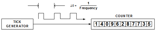
QPC uses a hardware counter as its basis. Hardware timers consist of three parts: a tick generator, a counter that counts the ticks, and a means of retrieving the counter value. The characteristics of these three components determine the resolution, precision, accuracy, and stability of QPC.
If a hardware generator provides ticks at a constant rate, time intervals can be measured by simply counting these ticks. The rate at which the ticks are generated is called the frequency and expressed in Hertz (Hz). The reciprocal of the frequency is called the period or tick interval and is expressed in an appropriate International System of Units (SI) time unit (for example, second, millisecond, microsecond, or nanosecond).
The resolution of the timer is equal to the period. Resolution determines the ability to distinguish between any two time stamps and places a lower bound on the smallest time intervals that can be measured. This is sometimes called the tick resolution.
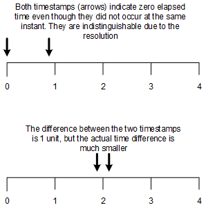
Digital measurement of time introduces a measurements uncertainty of В± 1 tick because the digital counter advances in discrete steps, while time is continuously advancing. This uncertainty is called a quantization error. For typical time-interval measurements, this effect can often be ignored because the quantizing error is much smaller than the time interval being measured.

However, if the period being measured is small and approaches the resolution of the timer, you will need to consider this quantizing error. The size of the error introduced is that of one clock period.
The following two diagrams illustrate the impact of the В± 1 tick uncertainty by using a timer with a resolution of 1 time unit.
QueryPerformanceFrequency returns the frequency of QPC, and the period and resolution are equal to the reciprocal of this value. The performance counter frequency that QueryPerformanceFrequency returns is determined during system initialization and doesn’t change while the system is running.
Cases might exist where QueryPerformanceFrequency doesn’t return the actual frequency of the hardware tick generator. For example, in many cases, QueryPerformanceFrequency returns the TSC frequency divided by 1024; and on Hyper-V, the performance counter frequency is always 10 MHz when the guest virtual machine runs under a hypervisor that implements the hypervisor version 1.0 interface. As a result, don’t assume that QueryPerformanceFrequency will return the precise TSC frequency.
QueryPerformanceCounter reads the performance counter and returns the total number of ticks that have occurred since the Windows operating system was started, including the time when the machine was in a sleep state such as standby, hibernate, or connected standby.
These examples show how to calculate the tick interval and resolution and how to convert the tick count into a time value.
Example 1
QueryPerformanceFrequency returns the value 3,125,000 on a particular machine. What is the tick interval and resolution of QPC measurements on this machine? The tick interval, or period, is the reciprocal of 3,125,000, which is 0.000000320 (320 nanoseconds). Therefore, each tick represents the passing of 320 nanoseconds. Time intervals smaller than 320 nanoseconds can’t be measured on this machine.
Tick Interval = 1/(Performance Frequency)
Tick Interval = 1/3,125,000 = 320 ns
Example 2
On the same machine as the preceding example, the difference of the values returned from two successive calls to QPC is 5. How much time has elapsed between the two calls? 5 ticks multiplied by 320 nanoseconds yields 1.6 microseconds.
ElapsedTime = Ticks * Tick Interval
ElapsedTime = 5 * 320 ns = 1.6 Ојs
It takes time to access (read) the tick counter from software, and this access time can reduce the precision of the of the time measurement. This is because the minimum interval time (the smallest time interval that can be measured) is the larger of the resolution and the access time.
Precision = MAX [ Resolution, AccessTime]
For example, consider a hypothetical hardware timer with a 100 nanosecond resolution and an 800 nanosecond access time. This might be the case if the platform timer were used instead of the TSC register as the basis of QPC. Thus, the precision would be 800 nanoseconds not 100 nanoseconds as shown in this calculation.
Precision = MAX [800 ns,100 ns] = 800 ns
These two figures depict this effect.
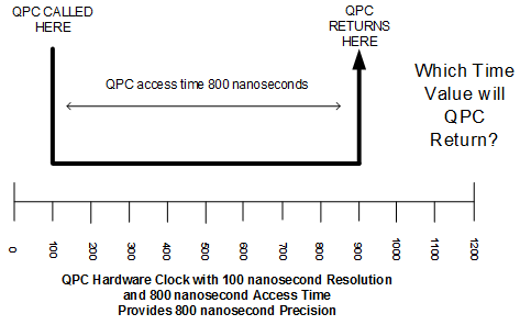
If the access time is greater than the resolution, don’t try to improve the precision by guessing. In other words, it’s an error to assume that the time stamp is taken precisely in the middle, or at the beginning or the end of the call.
By contrast, consider the following example in which the QPC access time is only 20 nanoseconds and the hardware clock resolution is 100 nanoseconds. This might be the case if the TSC register was used as the basis for QPC. Here the precision is limited by the clock resolution.
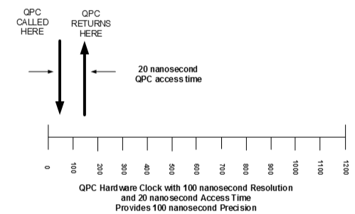
In practice, you can find time sources for which the time required to read the counter is larger or smaller than the resolution. In either case, the precision will be the larger of the two.
This table provides info on the approximate resolution, access time, and precision of a variety of clocks. Note that some of the values will vary with different processors, hardware platforms, and processor speeds.
| Clock Source | Nominal Clock Frequency | Clock Resolution | Access Time (Typical) | Precision |
|---|---|---|---|---|
| PC RTC | 64 Hz | 15.625 milliseconds | N/A | N/A |
| Query performance counter using TSC with a 3 GHz processor clock | 3 MHz | 333 nanoseconds | 30 nanoseconds | 333 nanoseconds |
| RDTSC machine instruction on a system with a 3 GHz cycle time | 3 GHz | 333 picoseconds | 30 nanoseconds | 30 nanoseconds |
Because QPC uses a hardware counter, when you understand some basic characteristics of hardware counters, you gain understanding about the capabilities and limitations of QPC.
The most commonly used hardware tick generator is a crystal oscillator. The crystal is a small piece of quartz or other ceramic material that exhibits piezoelectric characteristics that provide an inexpensive frequency reference with excellent stability and accuracy. This frequency is used to generate the ticks counted by the clock.
The accuracy of a timer refers to the degree of conformity to a true or standard value. This depends primarily on the crystal oscillator’s ability to provide ticks at the specified frequency. If the frequency of oscillation is too high, the clock will ‘run fast’, and measured intervals will appear longer than they really are; and if the frequency is too low, the clock will ‘run slow’, and measured intervals will appear shorter than they really are.
For typical time-interval measurements for short duration (for example, response time measurements, network latency measurements, and so on), the accuracy of the hardware oscillator is usually sufficient. However, for some measurements the oscillator frequency accuracy becomes important, particularly for long time intervals or when you want to compare measurements taken on different machines. The remainder of this section explores the effects of the oscillator accuracy.
The crystals’ frequency of oscillation is set during the manufacturing process and is specified by the manufacturer in terms of a specified frequency plus or minus a manufacturing tolerance expressed in ‘parts per million’ (ppm), called the maximum frequency offset. A crystal with a specified frequency of 1,000,000 Hz and a maximum frequency offset of В± 10 ppm would be within specification limits if its actual frequency were between 999,990 Hz and 1,000,010 Hz.
By substituting the phrase parts per million with microseconds per second, we can apply this frequency offset error to time-interval measurements. An oscillator with a + 10 ppm offset would have an error of 10 microseconds per second. Accordingly, when measuring a 1 second interval, it would run fast and measure a 1 second interval as 0.999990 seconds.
A convenient reference is that a frequency error of 100 ppm causes an error of 8.64 seconds after 24 hours. This table presents the measurement uncertainty due to the accumulated error for longer time intervals.
| Time interval duration | Measurement uncertainty due to accumulated error with +/- 10 PPM frequency tolerance |
|---|---|
| 1 microsecond | В± 10 picoseconds (10-12) |
| 1 millisecond | В± 10 nanoseconds (10-9) |
| 1 second | В± 10 microseconds |
| 1 hour | В± 60 microseconds |
| 1 day | В± 0.86 seconds |
| 1 week | В± 6.08 seconds |
The preceding table shows that for small time intervals the frequency offset error can often be ignored. However for long time intervals, even a small frequency offset can result in a substantial measurement uncertainty.
Crystal oscillators that are used in personal computers and servers are typically manufactured with a frequency tolerance of В± 30 to 50 parts per million, and rarely, crystals can be off by as much as 500 ppm. Although crystals with much tighter frequency offset tolerances are available, they are more expensive and thus are not used in most computers.
To reduce the adverse effects of this frequency offset error, recent versions of Windows, particularly WindowsВ 8, use multiple hardware timers to detect the frequency offset and compensate for it to the extent possible. This calibration process is performed when Windows is started.
As the following examples show, the frequency offset error of a hardware clock influences the achievable accuracy, and the resolution of the clock can be less important.

Example 1
Suppose you perform time-interval measurements by using a 1 MHz oscillator, which has a resolution of 1 microsecond, and a maximum frequency offset error of В±50 ppm. Now, let us suppose the offset is exactly +50 ppm. This means that the actual frequency would be 1,000,050 Hz. If we measured a time interval of 24 hours, our measurement would be 4.3 seconds too short (23:59:55.700000 measured versus 24:00:00.000000 actual).
Seconds in a day = 86400
Frequency offset error = 50 ppm = 0.00005
86,400 seconds * 0.00005 = 4.3 seconds
Example 2
Suppose the processor TSC clock is controlled by a crystal oscillator and has specified frequency of 3 GHz. This means that the resolution would be 1/3,000,000,000 or about 333 picoseconds. Assume the crystal used to control the processor clock has a frequency tolerance of В±50 ppm and is actually +50 ppm. In spite of the impressive resolution, a time-interval measurement of 24 hours will still be 4.3 seconds too short. (23:59:55.7000000000 measured versus 24:00:00.0000000000 actual).
Seconds in a day = 86400
Frequency offset error = 50 ppm = 0.00005
86,400 seconds * 0.00005 = 4.3 seconds
This shows that a high resolution TSC clock doesn’t necessarily provide more accurate measurements than a lower resolution clock.
Example 3
Consider using two different computers to measure the same 24 hour time interval. Both computers have an oscillator with a maximum frequency offset of В± 50 ppm. How far apart can the measurement of the same time interval on these two systems be? As in the previous examples, В± 50 ppm yields a maximum error of В± 4.3 seconds after 24 hours. If one system runs 4.3 seconds fast, and the other 4.3 seconds slow, the maximum error after 24 hours could be 8.6 seconds.
Seconds in a day = 86400
Frequency offset error = В±50 ppm = В±0.00005
В±(86,400 seconds * 0.00005) = В±4.3 seconds
Maximum offset between the two systems = 8.6 seconds
In summary, the frequency offset error becomes increasingly important when measuring long time intervals and when comparing measurements between different systems.
The stability of a timer describes whether the tick frequency changes over time, for example as the result of temperatures changes. Quartz crystals used as the tick generators on computers will exhibit small changes in frequency as a function of temperature. The error caused by thermal drift is typically small compared to the frequency offset error for common temperature ranges. However, designers of software for portable equipment or equipment subject to large temperature fluctuations might need to consider this effect.
Hardware timer info
TSC Register
Some Intel and AMD processors contain a TSC register that is a 64-bit register that increases at a high rate, typically equal to the processor clock. The value of this counter can be read through the RDTSC or RDTSCP machine instructions, providing very low access time and computational cost in the order of tens or hundreds of machine cycles, depending upon the processor.
Although the TSC register seems like an ideal time stamp mechanism, here are circumstances in which it can’t function reliably for timekeeping purposes:
- Not all processors have TSC registers, so using the TSC register in software directly creates a portability problem. (Windows will select an alternative time source for QPC in this case, which avoids the portability problem.)
- Some processors can vary the frequency of the TSC clock or stop the advancement of the TSC register, which makes the TSC unsuitable for timing purposes on these processors. These processors are said to have non-invariant TSC registers. (Windows will automatically detect this, and select an alternative time source for QPC).
- On multi-processor or multi-core systems, some processors and systems are unable to synchronize the clocks on each core to the same value. (Windows will automatically detect this, and select an alternative time source for QPC).
- On some large multi-processor systems, you might not be able to synchronize the processor clocks to the same value even if the processor has an invariant TSC. (Windows will automatically detect this, and select an alternative time source for QPC).
- Some processors will execute instructions out of order. This can result in incorrect cycle counts when RDTSC is used to time instruction sequences because the RDTSC instruction might be executed at a different time than specified in your program. The RDTSCP instruction has been introduced on some processors in response to this problem.
Like other timers, the TSC is based on a crystal oscillator whose exact frequency is not known in advance and that has a frequency offset error. Thus before it can be used, it must be calibrated using another timing reference.
During system initialization, Windows checks if the TSC is suitable for timing purposes and performs the necessary frequency calibration and core synchronization.
PM Clock
The ACPI timer, also known as the PM clock, was added to the system architecture to provide reliable time stamps independently of the processors speed. Because this was the single goal of this timer, it provides a time stamp in a single clock cycle, but it doesn’t provide any other functionality.
HPET Timer
The High Precision Event Timer (HPET) was developed jointly by Intel and Microsoft to meet the timing requirements of multimedia and other time-sensitive applications. HPET support has been in Windows since WindowsВ Vista, and WindowsВ 7 and WindowsВ 8 Hardware Logo certification requires HPET support in the hardware platform.