- Как правильно включить USB порты в БИОСе
- Вход в настройки BIOS
- Вход в настройки BIOS / UEFI новейших ПК
- Навигация в меню
- AMI BIOS
- Phoenix AwardBIOS
- AMI BIOS for Asus
- Настройки Windows
- Видео: как настроить любой BIOS на загрузку с USB флешки
- USB configuration descriptors
- How to get the configuration descriptor
Как правильно включить USB порты в БИОСе
Если на вашем ПК не работают порты USB, а настройки Windows и обновление драйверов не помогают, возможно, контроллер был отключен в БИОСе. В этом случае вам потребуется зайти в меню конфигураций и включить все назад.
Существует множество различных версий BIOS со своими интерфейсами и тонкостями работы. Также на вашем компьютере может работать более современный комплекс — UEFI, который поддерживает полноценный графический интерфейс. В данной статье рассмотрены дистрибутивы, которые чаще всего устанавливаются на материнские платы.
Вход в настройки BIOS
Чтобы приступить к изменению конфигурации, нужно попасть в соответствующее меню. Его можно открыть во время включения персонального компьютера — до того, как началась загрузка Windows с жесткого диска.
Включите ПК. В случае, если он уже работает: перезагрузите. Дождитесь звукового сигнала спикера: короткий одиночный гудок свидетельствует о том, что все внутренние компоненты, необходимые для работы компьютера, обнаружены.
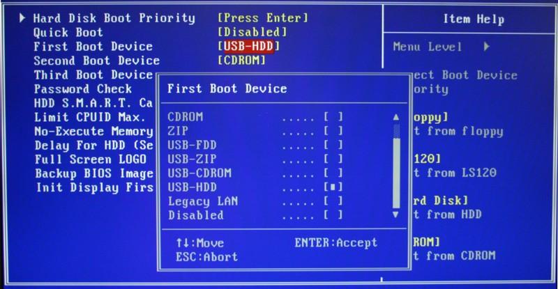
Теперь необходимо нажать горячую клавишу для вызова конфигурации. Это нужно сделать до смены экрана. Если вы не успели, и началась загрузка Windows — перезагружайтесь. Клавиши зависят от модели установленной материнской платы и версии прошивки BIOS. Узнать ее можно в руководстве пользователя, которое прилагается к материнке, на официальном сайте производителя или посмотреть на экране вашего ПК при его загрузке:
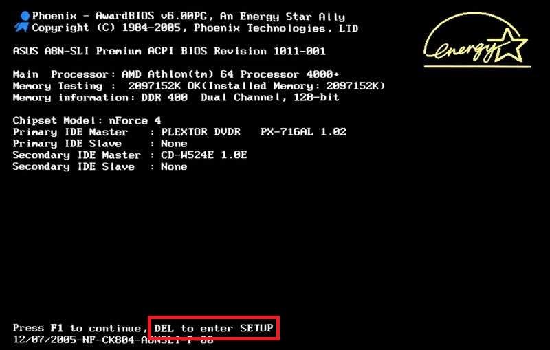
Если вы не знаете модель платы — ничего страшного. Просто попробуйте нажимать следующие клавиши: Tab , Delete , Esc , F1 , F2 , F8 , F10 , F11 , F12 . Одна из них наверняка подойдет.
Необязательно пробовать только 1 вариант за раз. Вы без проблем можете быстро нажать все кнопки из списка. Одна из них подойдет и запустит настройки БИОСа, а остальные будут проигнорированы.
Вход в настройки BIOS / UEFI новейших ПК
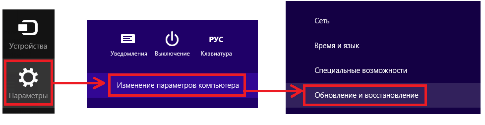
- Проведите мышью сверху-вниз или снизу-вверх по правому краю экрана и в появившемся окне нажмите «Параметры».
- Кликните на надпись «Изменение параметров компьютера»
- Нажмите «Обновление и восстановление».

- Далее: «Восстановление».
- В разделе «Особые варианты загрузки» нажмите кнопку Перезагрузить сейчас .
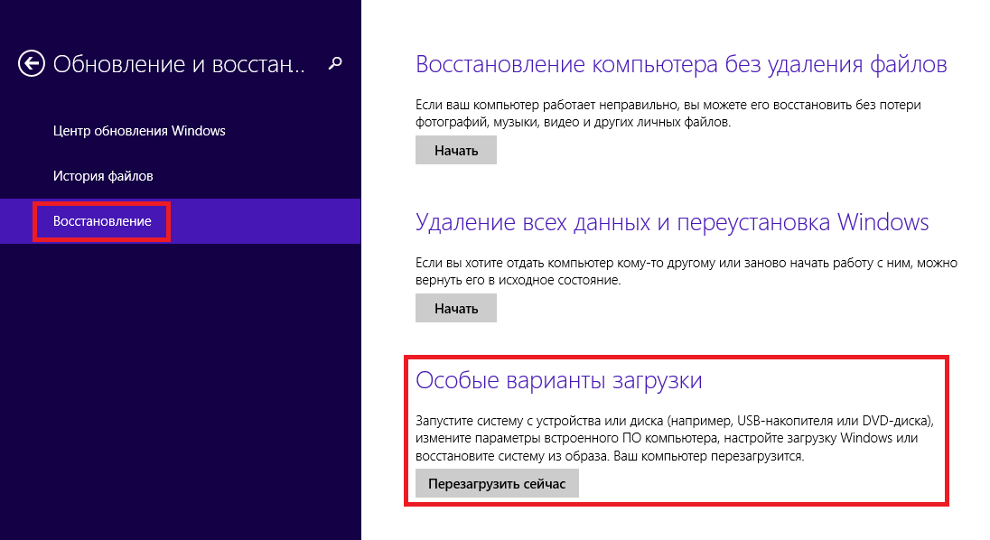
Ваш компьютер или ноутбук перезагрузится в режиме настройки. После перезагрузки ПК вы также сможете выбрать вариант запуска с USB-накопителя или DVD-диска.
Навигация в меню
Практически все версии БИОС лишены графического интерфейса. Это значит, что вам придется работать только с помощью клавиатуры, как, например, в консоли Windows. Навигация осуществляется с помощью стрелок «вверх-вниз» и «вправо»-«влево». Чтобы открыть какой-либо раздел, используйте клавишу Enter , чтобы вернуться назад – «Escape». Небольшая памятка по используемым клавишам всегда показывается на экране.
Комплекс микропрограмм UEFI устанавливается на самых дорогих и мощных материнских платах. Он поддерживает большее количество драйверов и умеет работать с мышью. Его интерфейс будет привычен пользователям Windows и других современных операционных систем.

Каждая версия обладает собственным интерфейсом и наборами опций. Даже названия одних и тех же параметров могут различаться. Далее в статье описано несколько популярных релизов БИОС.
AMI BIOS
Очень распространенный вариант, который можно встретить на многих современных компьютерах. Главное меню разделено на 2 части: список категорий и различные действия, вроде выхода или сохранения. Вы будете работать с левой частью.

Вам необходимо перейти в раздел, который называется «Integrated Peripherals». Русскоязычной версии интерфейса нет, поэтому все команды только на английском. С помощью стрелки «Вниз» выделите данный пункт и нажмите Enter .
Здесь нужно включить (Enabled) 4 опции:
- USB EHCI controller – основной контроллер. Если на материнской плате есть порты версии 3.0, этот пункт будет разделен на 2 части: «Controller» и «Controller 2.0»;
- USB Keyboard Support – поддержка клавиатур;
- USB Mouse Support – поддержка мышек;
- Legacy USB storage detect – работа с внешними хранилищами данных: флешками, дисковыми накопителями, дисками смартфонов и цифровых фотоаппаратов.

В некоторых старых версиях присутствует всего 2 пункта «USB controller» и «Legacy USB storage support».
Когда закончите с настройками, нажмите клавишу F10 , чтобы сохранить внесенные изменения и перезагрузить компьютер.
Phoenix AwardBIOS
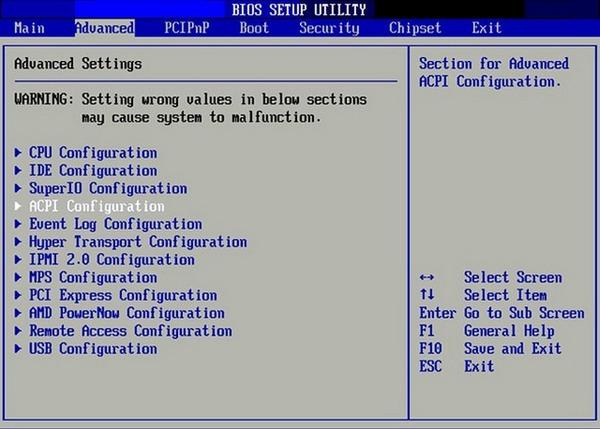
Другая популярная версия, которую часто можно встретить на современных ноутбуках. Не имеет главной страницы, как AMI, но снабжен удобными тематическими закладками вверху. Перемещаться между разделами можно с помощью стрелок «влево»-«вправо», а между пунктами — с помощью «вверх» и «вниз».
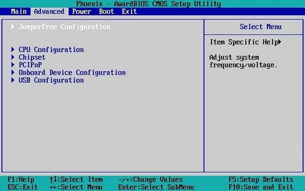
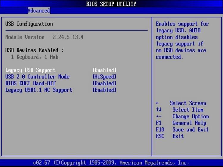
Перейдите в раздел «Advanced» с помощью стрелки «Вправо». В ней найдите категорию «USB configuration». Все пункты этого раздела необходимо перевести в положение «Enabled». В некоторых версиях категория «USB configuration» может находиться во вкладке «Peripherals» а не в «Advanced».
Для завершения работы в меню нажмите F10 и подтвердите выход.
AMI BIOS for Asus
Версия AMI, используемая на ноутбуках Asus. Внешне очень похожа на Phoenix — аналогичная панель закладок. Настройки USB находятся в разделе «Advanced». Перейдите туда, включите все опции и выйдите с помощью кнопки F10 .
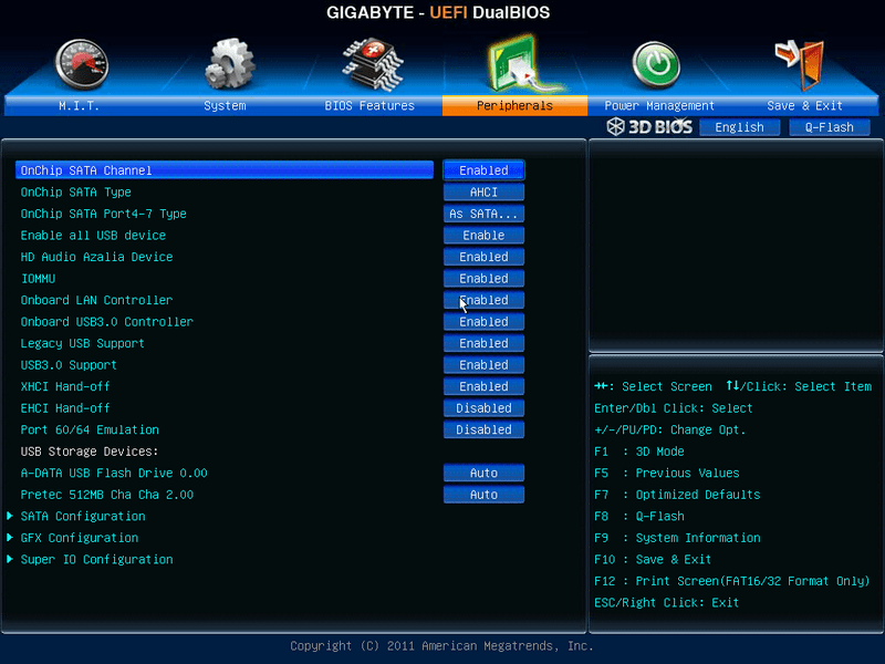
Вопреки распространенному мнению, UEFI — не часть BIOS. Его скорее можно назвать более продвинутым, но менее популярным конкурентом. Существует большое количество различных версий, каждая со своими интерфейсами. Однако здесь управление похоже на привычную Windows, поэтому вы без труда найдете нужные опции.
Настройки Windows
Если на уровне БИОСа все порты и контроллеры включены, но USB порты все-равно не работают, возможно, проблема в настройках вашей системы Windows.
Во-первых, попробуйте просто отключить и подключить устройство заново. Это вызовет проверку корректности драйверов. Если с ними что-то не так, Windows постарается переустановить их.
Если при переподключении ничего не происходит — попробуйте включить контроллер в реестре Windows. Для этого необходимо сделать следующее:
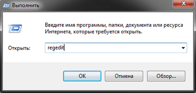
- Вызовите диалог «Выполнить» с помощью Win + R (либо через «Пуск»: в XP и 7-ке щелкнув по ней левой кнопкой мыши, а в 8 и 10 версиях — правой кнопкой мыши).
- Введите regedit и нажмите OK .
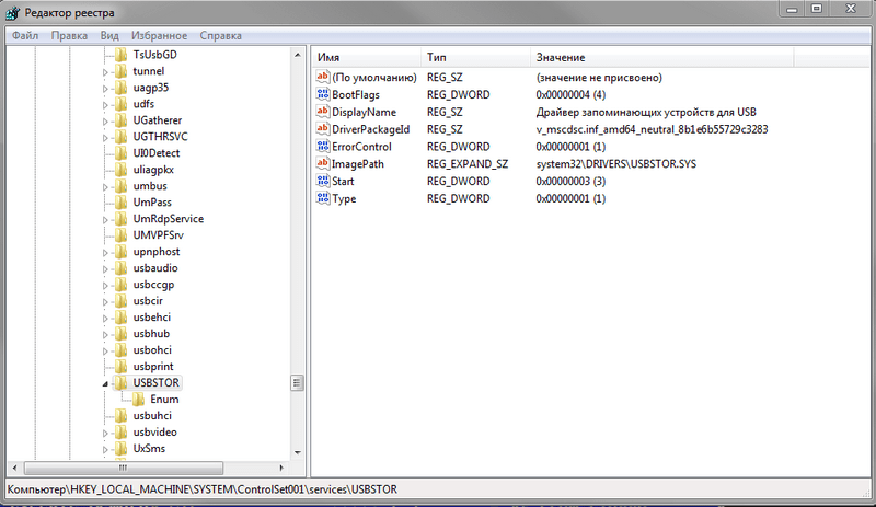
- Перейдите в раздел «HKEY_LOCAL_MACHINE \ SYSTEM \ CurrentControlSet \ Services \ USBSTOR».
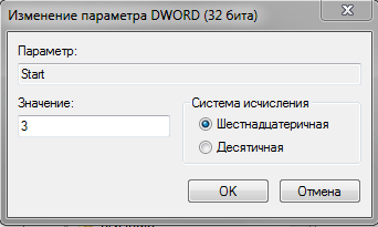
- Дважды кликните по записи «Start», чтобы открыть окно редактирования.
- Измените значение на «3». При любых других значения параметра, USB порты работать не будут.
- Нажмите OK и закройте редактор.
Видео: как настроить любой BIOS на загрузку с USB флешки
USB configuration descriptors
A USB device exposes its capabilities in the form of a series of interfaces called a USB configuration. Each interface consists of one or more alternate settings, and each alternate setting is made up of a set of endpoints. This topic describes the various descriptors associated with a USB configuration.
A USB configuration is described in a configuration descriptor (see USB_CONFIGURATION_DESCRIPTOR structure). A configuration descriptor contains information about the configuration and its interfaces, alternate settings, and their endpoints. Each interface descriptor or alternate setting is described in a USB_INTERFACE_DESCRIPTOR structure. In a configuration, each interface descriptor is followed in memory by all of the endpoint descriptors for the interface and alternate setting. Each endpoint descriptor is stored in a USB_ENDPOINT_DESCRIPTOR structure.
For example, consider a USB webcam device described in USB Device Layout. The device supports a configuration with two interfaces, and the first interface (index 0) supports two alternate settings.
The following example shows the configuration descriptor for the USB webcam device:
The bConfigurationValue field indicates the number for the configuration defined in the firmware of the device. The client driver uses that number value to select an active configuration. For more information about USB device configuration, see How to Select a Configuration for a USB Device. A USB configuration also indicates certain power characteristics. The bmAttributes contains a bitmask that indicates whether the configuration supports the remote wake-up feature, and whether the device is bus-powered or self-powered. The MaxPower field specifies the maximum power (in milliamp units) that the device can draw from the host, when the device is bus-powered. The configuration descriptor also indicates the total number of interfaces (bNumInterfaces) that the device supports.
The following example shows the interface descriptor for Alternate Setting 0 of Interface 0 for the webcam device:
In the preceding example, note bInterfaceNumber and bAlternateSetting field values. Those fields contain index values that a client driver uses to activate the interface and one of its alternate settings. For activation, the driver sends a select-interface request to the USB driver stack. The driver stack then builds a standard control request (SET INTERFACE) and sends it to the device. Note the bInterfaceClass field. The interface descriptor or the descriptor for any of its alternate settings specifies a class code, subclass, and protocol. The value of 0x0E indicates that the interface is for the video device class. Also, notice the iInterface field. That value indicates that there are two string descriptors appended to the interface descriptor. String descriptors contain Unicode descriptions that are used during device enumeration to identify the functionality. For more information about string descriptors, see USB String Descriptors.
Each endpoint, in an interface, describes a single stream of input or output for the device. A device that supports streams for different kinds of functions has multiple interfaces. A device that supports several streams that pertain to a function can support multiple endpoints on a single interface.
All types of endpoints (except the default endpoint) must provide endpoint descriptors so that the host can get information about endpoint. An endpoint descriptor includes information, such as its address, type, direction, and the amount of data the endpoint can handle. The data transfers to the endpoint are based on that information.
The following example shows an endpoint descriptor for the webcam device:
The bEndpointAddress field specifies the unique endpoint address that contains the endpoint number (Bits 3..0) and the direction of the endpoint (Bit 7). By reading those values in the preceding example, we can determine that the descriptor describes an IN endpoint whose endpoint number is 2. The bmAttributes attribute indicates that the endpoint type is isochronous. The wMaxPacketSizefield indicates the maximum number of bytes that the endpoint can send or receive in a single transaction. Bits 12..11 indicate the total number of transactions that can be sent per microframe. The bInterval indicates how often the endpoint can send or receive data.
How to get the configuration descriptor
The configuration descriptor is obtained from the device through a standard device request (GET_DESCRIPTOR), which is sent as a control transfer by the USB driver stack. A USB client driver can initiate the request in one of the following ways:
If the device supports only one configuration, the easiest way is to call the framework-provided WdfUsbTargetDeviceRetrieveConfigDescriptor method.
For a device that supports multiple configurations, if the client driver wants to get the descriptor of the configuration other than the first, the driver must submit an URB. To submit an URB, the driver must allocate, format, and then submit the URB to the USB driver stack.
To allocate the URB, the client driver must call the WdfUsbTargetDeviceCreateUrb method. The method receives a pointer to an URB allocated by the USB driver stack.
To format the URB, the client driver can use the UsbBuildGetDescriptorRequest macro. The macro sets all the necessary information in the URB, such as the device-defined configuration number for which to retrieve the descriptor. The URB function is set to URB_FUNCTION_GET_DESCRIPTOR_FROM_DEVICE (see _URB_CONTROL_DESCRIPTOR_REQUEST) and the type of descriptor is set to USB_CONFIGURATION_DESCRIPTOR_TYPE. By using the information contained in the URB, the USB driver stack builds a standard control request and sends it to the device.
To submit the URB, the client driver must use a WDF request object. To send the request object to the USB driver stack asynchronously, the driver must call the WdfRequestSendmethod. To send it synchronously, call the WdfUsbTargetDeviceSendUrbSynchronously method.
Within a USB configuration, the number of interfaces and their alternate settings are variable. Therefore, it’s difficult to predict the size of buffer required to hold the configuration descriptor. The client driver must collect all that information in two steps. First, determine what size buffer required to hold all of the configuration descriptor, and then issue a request to retrieve the entire descriptor. A client driver can get the size in one of the following ways:
To obtain the configuration descriptor by calling WdfUsbTargetDeviceRetrieveConfigDescriptor, perform these steps:
- Get the size of buffer required to hold all of the configuration information by calling WdfUsbTargetDeviceRetrieveConfigDescriptor. The driver must pass NULL in the buffer, and a variable to hold the size of the buffer.
- Allocate a larger buffer based on the size received through the previous WdfUsbTargetDeviceRetrieveConfigDescriptor call.
- Call WdfUsbTargetDeviceRetrieveConfigDescriptor again and specify a pointer to the new buffer allocated in step 2.
To obtain the configuration descriptor by submitting an URB, perform these steps:
- Allocate an URB by calling the WdfUsbTargetDeviceCreateUrb method.
- Format the URB by calling the UsbBuildGetDescriptorRequest macro. The transfer buffer of the URB must point to a buffer large enough to hold a USB_CONFIGURATION_DESCRIPTOR structure.
- Submit the URB as a WDF request object by calling WdfRequestSend or WdfUsbTargetDeviceSendUrbSynchronously.
- After the request completes, check the wTotalLength member of USB_CONFIGURATION_DESCRIPTOR. That value indicates the size of the buffer required to contain a full configuration descriptor.
- Allocate a larger buffer based on the size retrieved in wTotalLength.
- Issue the same request with the larger buffer.
The following example code shows the UsbBuildGetDescriptorRequest call for a request to get configuration information for the i-th configuration:
When the device returns the configuration descriptor, the request buffer is filled with interface descriptors for all alternate settings, and endpoint descriptors for all endpoints within a particular alternate setting. For the device described in USB Device Layout, the following diagram illustrates how configuration information is laid out in memory.

The zero-based bInterfaceNumber member of USB_INTERFACE_DESCRIPTOR distinguishes interfaces within a configuration. For a given interface, the zero-based bAlternateSetting member distinguishes between alternate settings of the interface. The device returns interface descriptors in order of bInterfaceNumber values and then in order of bAlternateSetting values.
To search for a given interface descriptor within the configuration, the client driver can call USBD_ParseConfigurationDescriptorEx. In the call, the client driver provides a starting position within the configuration. Optionally the driver can specify an interface number, an alternate setting, a class, a subclass, or a protocol. The routine returns a pointer to the next matching interface descriptor.
To examine a configuration descriptor for an endpoint or string descriptor, use the USBD_ParseDescriptors routine. The caller provides a starting position within the configuration and a descriptor type, such as USB_STRING_DESCRIPTOR_TYPE or USB_ENDPOINT_DESCRIPTOR_TYPE. The routine returns a pointer to the next matching descriptor.